SASS® 2400
Wetted-Wall Air Sampler Operational Details
Performance Overview
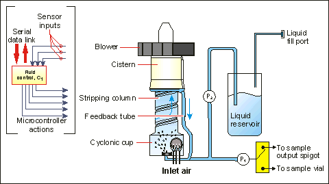
A schematic representation of the SASS 2400 is shown in Figure 1 below. The cyclone has four main sections: a cyclonic cup, stripping column, cistern, and water feedback loop. A high-efficiency, brushless centrifugal blower at the cyclone exit pulls air into the unit. When the SASS is turned on, the blower is activated and a water charge is injected into the cyclonic cup from a fresh water reservoir. Incoming air enters at the cup perimeter, creating strong vortex action and a rapidly swirling film of water on exposed surfaces. The water film passes across the air inlet region, forming a water curtain through which air must pass.

Concurrently, a centrally located port in the cup base injects additional water. This location is subject to high air shear, and fluid discharged from the port into the cup will be in the form of a fine spray. The cup plays a major role in collection of sub-micron particles and molecular species due to the intimate two-phase contact provided, whereas larger respirable particles are captured in both the cup and a stripping column to be described.
The air stream then flows from the cup into a stripping column connected to the cup’s upper surface. As air enters the smaller diameter stripping column it increases in rotational velocity, enhancing particulate collection through centrifugal action. The inner surface of the stripping column is also wet by fluid outflow from the cup. The airflow rate and column inside diameter have been designed so that adequate shear force is produced to create a cocurrent upward flow of water on the column wall. The stripping column is operated beyond the so-called ‘flooding limit,’ meaning that liquid introduced at the base of the column cannot flow opposite to the upwelling air, and, in fact, must flow up the stripping column.
Water flows from the stripping column into a larger diameter cistern section located above the stripping tube. Due to parasitic shear forces created by the rotating airflow, water transitioning from the tube to the cistern is flung outward to a water trap zone where a rapidly rotating water ring is formed. Water in the ring flows back to the cyclonic cup by way of a liquid feedback tube. This water is re-injected into the cup via the previously mentioned port, where it is once again available to collect additional particulates.
The nominal liquid sample inventory needed to wet all key surfaces is only 1.0 cc, and is automatically maintained by a proprietary liquid level control circuit described below. Fluid re-circulation rates have been measured to be in the range of 1 to 2 ml/minute. This means a typical 1 cc water inventory is re-circulated through the unit from 1 to 2 times per minute of operation.
Aerosol collection characteristics are similar to those of the SASS 2300, with significant particle retention over very long collection periods of up to several hours. Collection efficiency is typically 70% for three micron particles, decreasing to 50% at a particle size between 1 to 2 microns, and approaching a maximum of about 90% as particle size increases. The maximum particle size that can be collected is essentially unlimited. To prevent clogging of the liquid feedback tube, it is recommended that objects of greater than 1 mm diameter be excluded from capture through the use of an external filter or screen cover on the inlet.
Fluid Control Subsystem
The particle extraction process involves intimate mixing of incoming air with recirculating sample water. All water would be lost in a short time if no attempt were made to compensate for evaporation. To prevent dry out, the liquid volume is monitored with a proprietary sensor attached to the water feedback tube. When the sample water inventory falls below a preset level, a microprocessor-controlled peristaltic pump meters a small amount of clean water into the re-circulation loop from an onboard water reservoir to bring the level back to set point. Water inventories can be maintained at the nominal 1 cc setting with an accuracy of +/– 0.15 cc for periods of hours to days (U.S. Patent 6,532,835). Since the re-circulation loop does not use a mechanical pump, power consumption is minimized, delicate organisms are not damaged, and cleaning is simplified.
Samples may be removed at any time using an onboard peristaltic pump. When the unit is operated manually, air flow is stopped during the sample transfer process to allow fluid films to collect as a pool in the bottom of the unit. If the unit is being operated remotely via the serial digital link, air sampling may continue during the sample transfer process. The user can in either case elect to discharge the sample to an onboard sample vial or to a discharge spigot at the rear of the instrument.
Electronics
The microcontroller-based SASS 2400 has been designed to communicate with and be controlled by various triggers, bioanalyzers and data collection networks via its RS-232 serial data link. System firmware is located in flash memory and can be modified, customized and upgraded electronically at any time. There is no need to disassemble the unit. A program that operates under Windows® is supplied with the instrument that allows the SASS 2400 to be operated from a PC. This program also allows users to change a large number of default settings resident in flash memory, such as fan speed and liquid inventory- essentially customizing operation to their purposes.
Accessories
Air inlet and outlet ports feature an industry-standard screw thread that allows many different types of input and output hoses, nozzles and filters to be mounted to the unit. System electronics and firmware are designed for ease of customization. Please contact us if you are interested in adding CBRN International's BioLink™ for wireless communications, or modules that can provide GPS, weather data, visual surveillance, or thermal imaging, as examples.
Visit the SASS 2400 product page


